
Spooky 2x3
Overview
This guide will walk you over how to build the Boardsource spooky PCB.
Kit Contents
- 1 x Spooky PCB
- 1 x micro controller
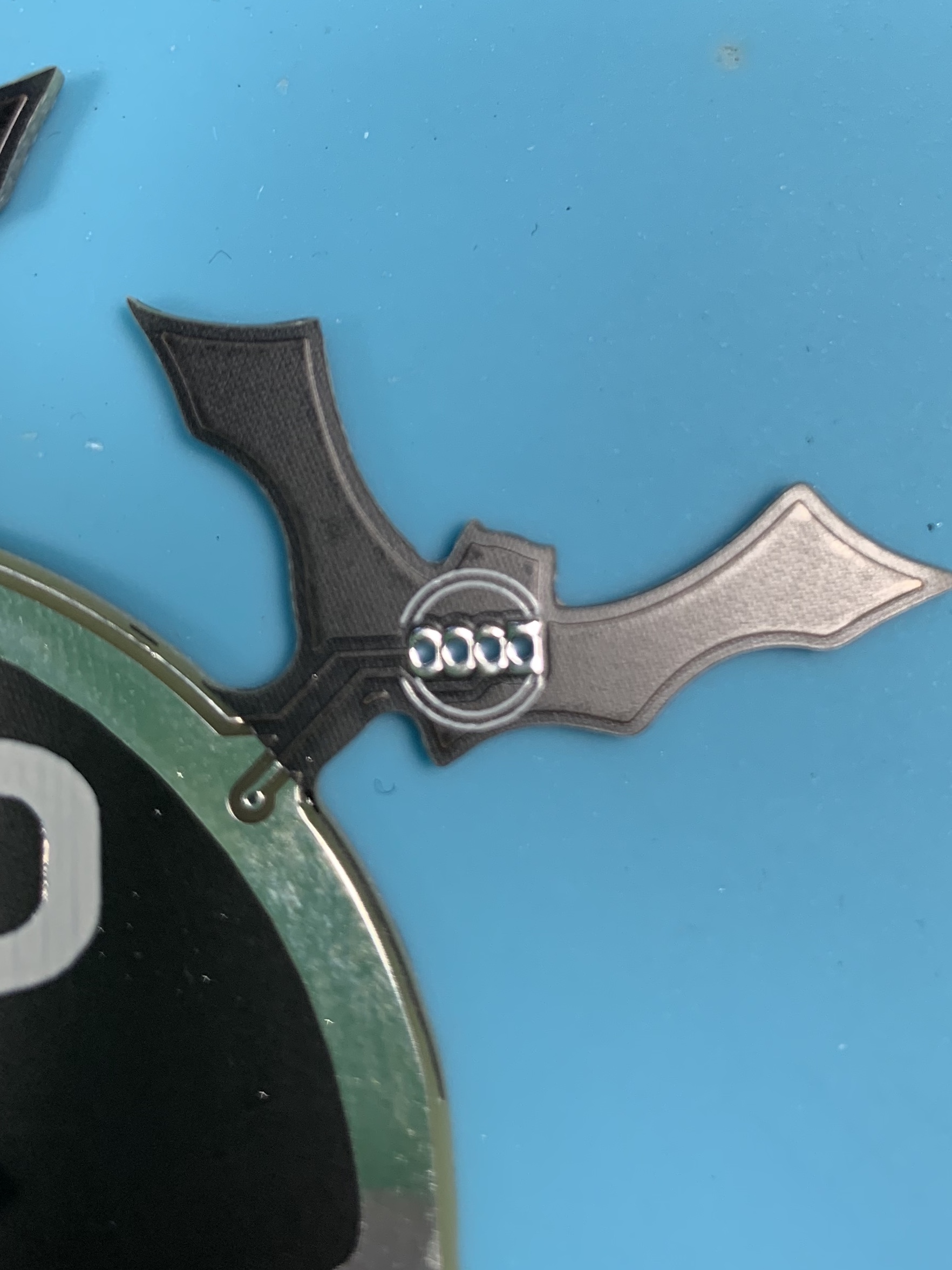
- 5 x (TH) RGB leds
- 6 x Hotswap sockets choc or mx
- 1 x OLED Screen
Step 1: Check Kit Contents
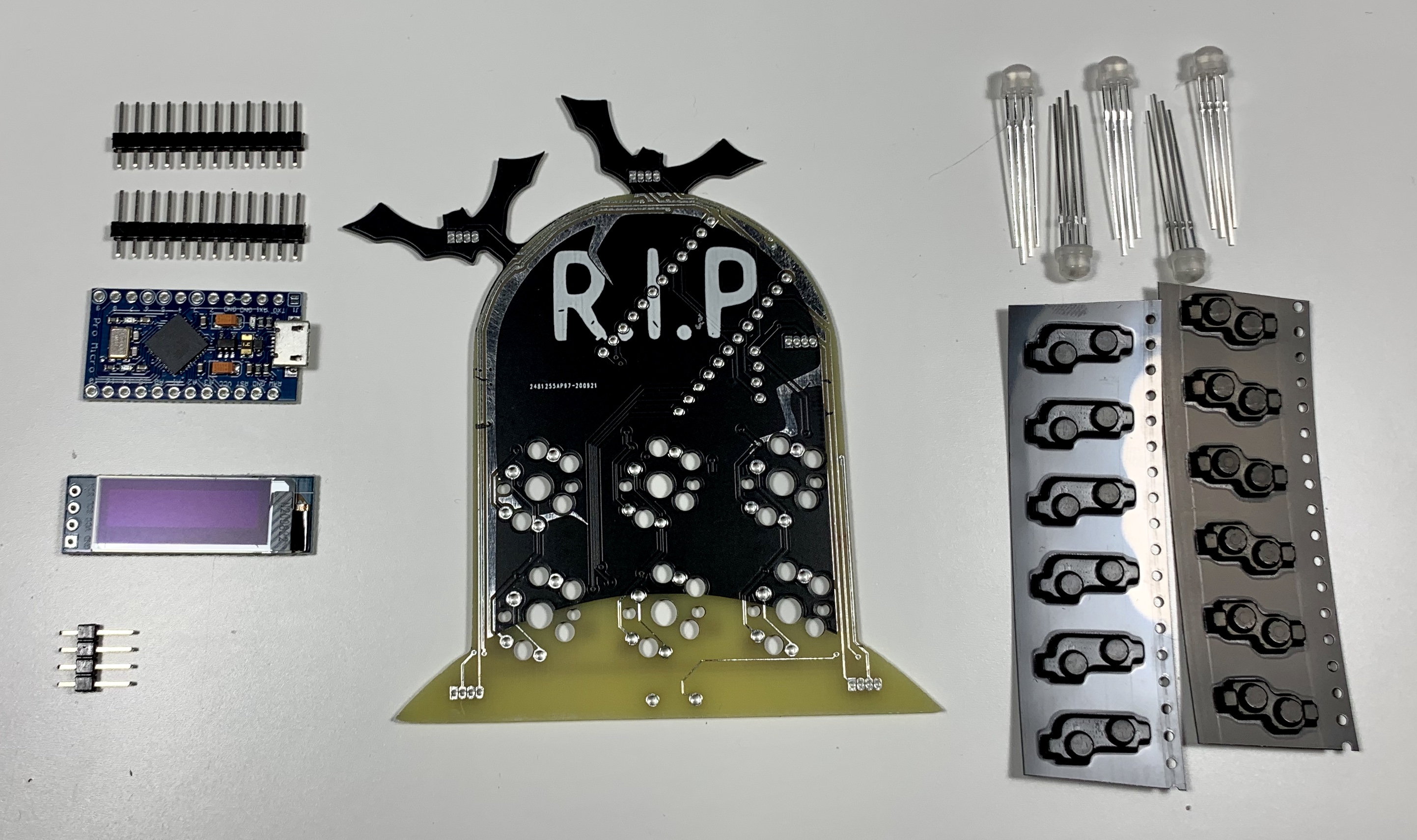
Prior to starting any build it is important to take a look at what you received and what you have in front of you. Nothing is more frustrating than getting halfway through a build and realizing you’re missing a single hotswap socket or a screw, or anything for that matter. If you think we forgot to ship something, or if you may have accidentally misplaced something, please reach out to us on Discord in the Help section, or Submit A Ticket in the My Account section of Boardsource.
Note: Boardsource often includes extras of certain items in our kits, it is not unusual to have an extra screw, hotswap socket, or diode. The quantities listed in the Kit Contents section at the beginning of this guide are the true accurate number of components needed to complete the build, if you have more than the listed quantities or have some leftover at the end it does not mean that you forgot something or built the kit improperly.
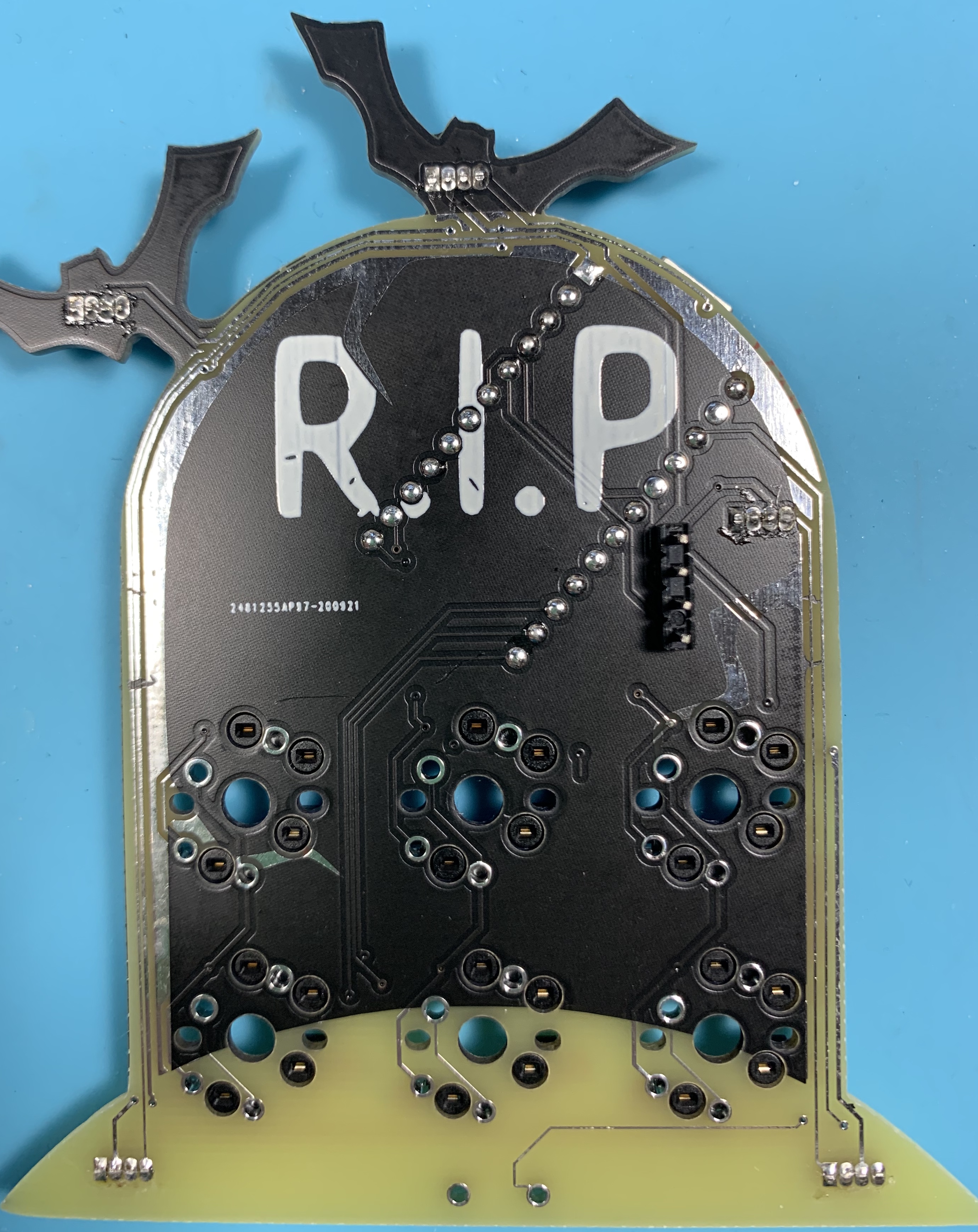
Step 2: Assemble the PCB
PCB Assembly - Prepare Hotswap Sockets
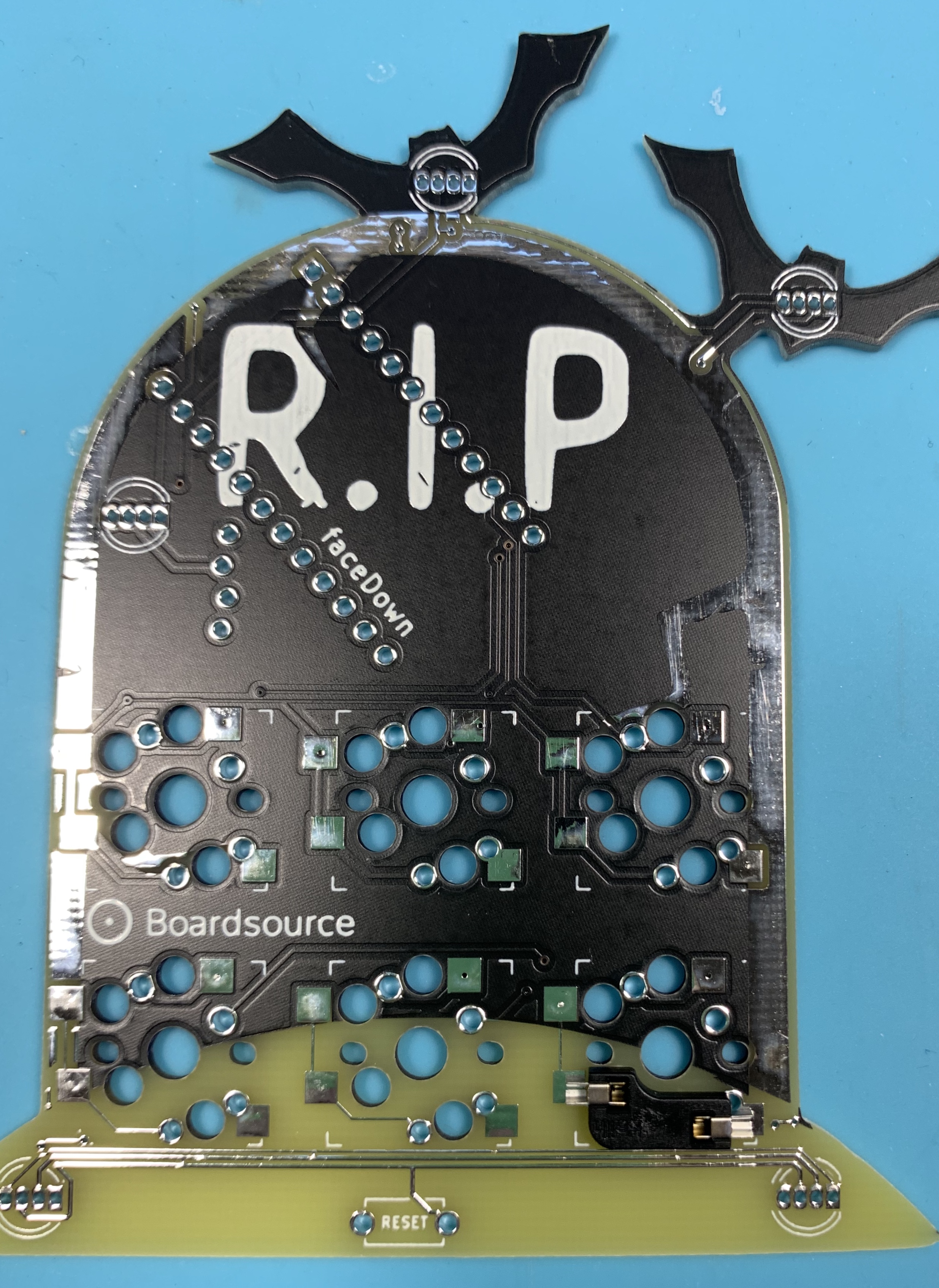 Place each hotswap socket into the designated place on the PCB. Hotswap sockets go on the back of the PCB. The back of the PCB is indicated by having solder points for the hotswap sockets, and the word faceDown.
Match up the solder points to the solder pads on the back of the PCB. You will know that the hotswap socket is oriented properly because no portion of the socket should overlap the hole in between the pads that allow for a switch post to pass through. If your sockets are oriented incorrectly, they will intersect that hole and your switch will not sit properly.
I like to place every hotswap socket prior to soldering, and then solder them all at once, but it is your decision on the order of operations there.
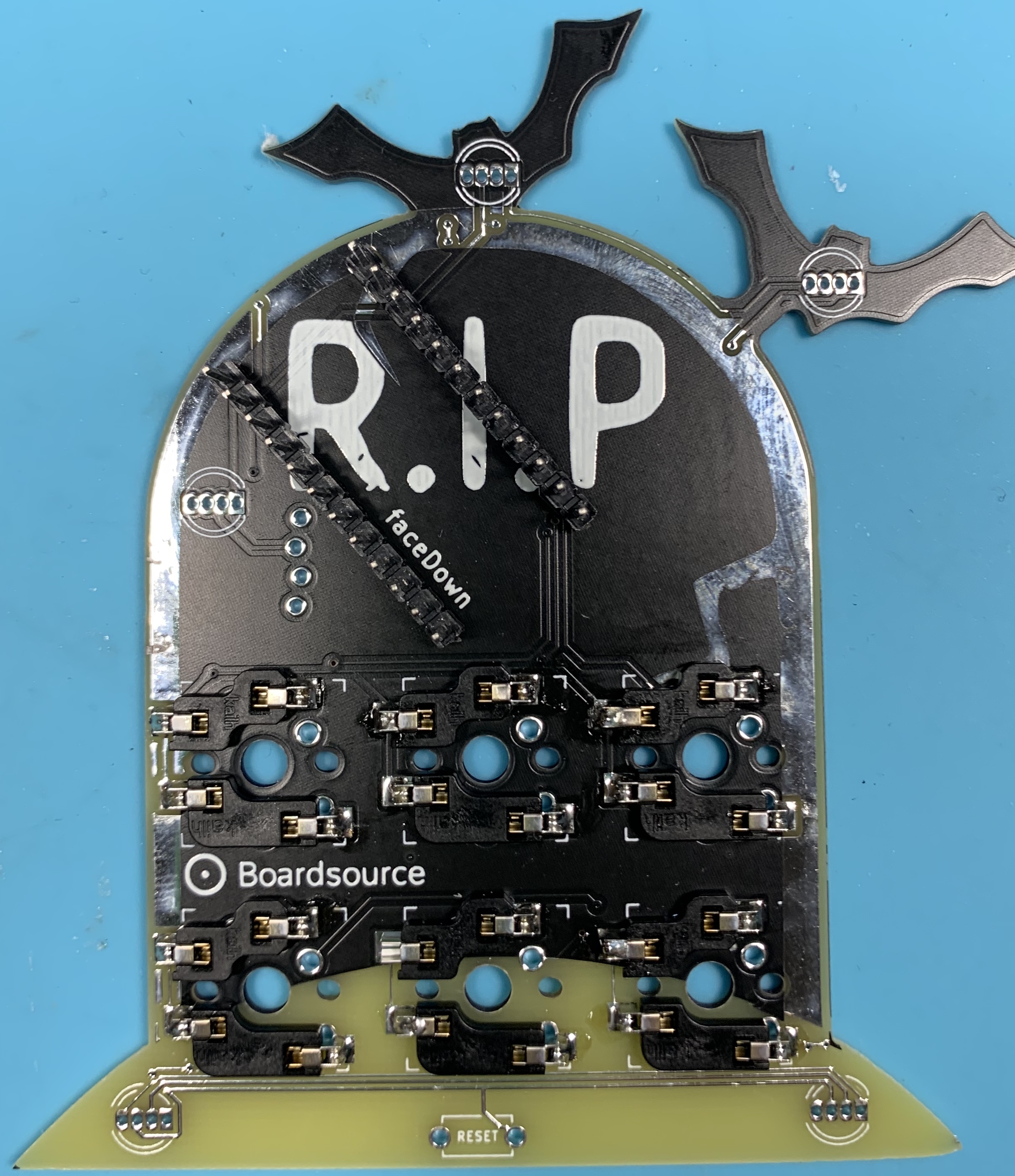
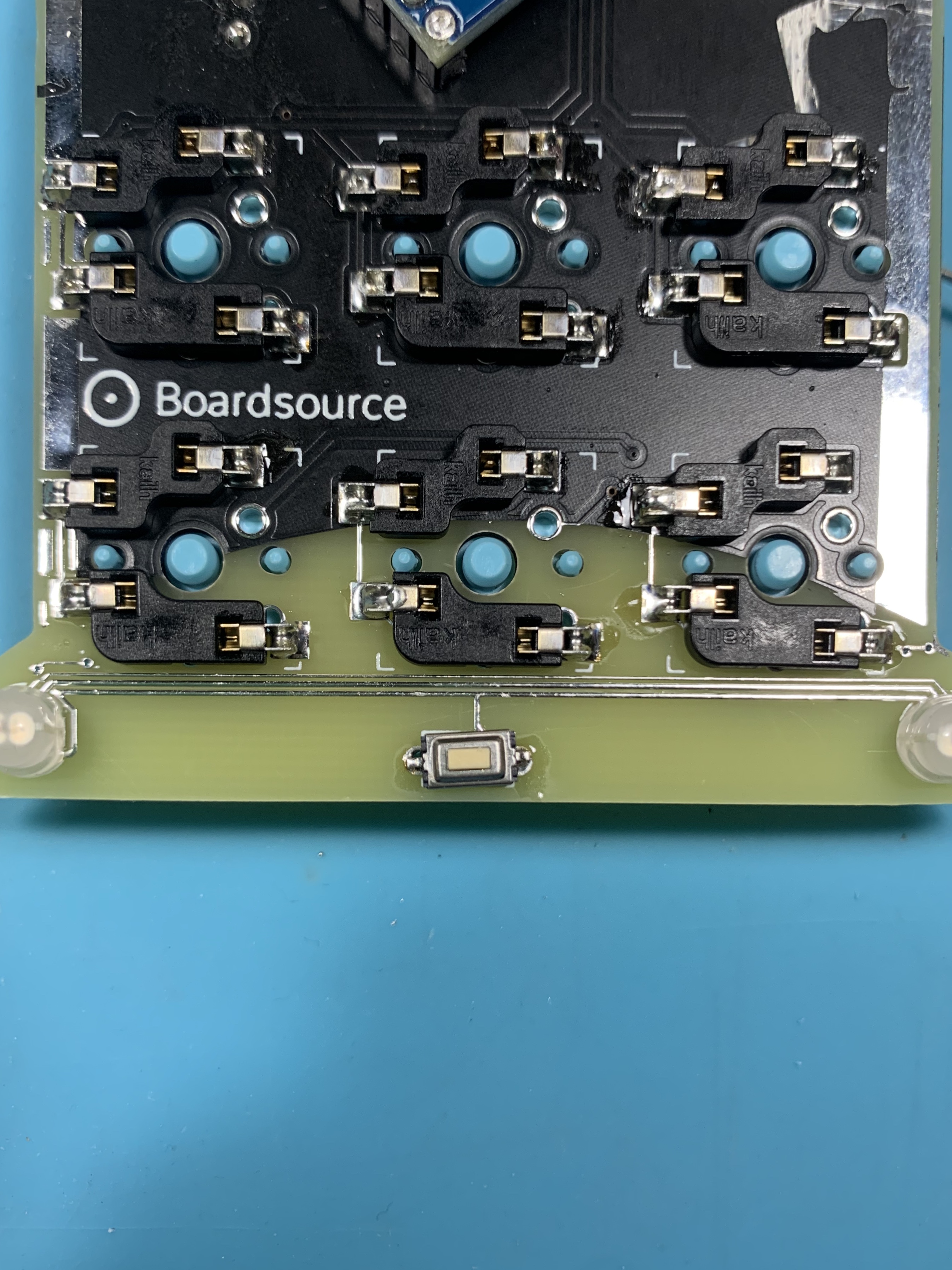
PCB Assembly - Solder Hotswap Sockets
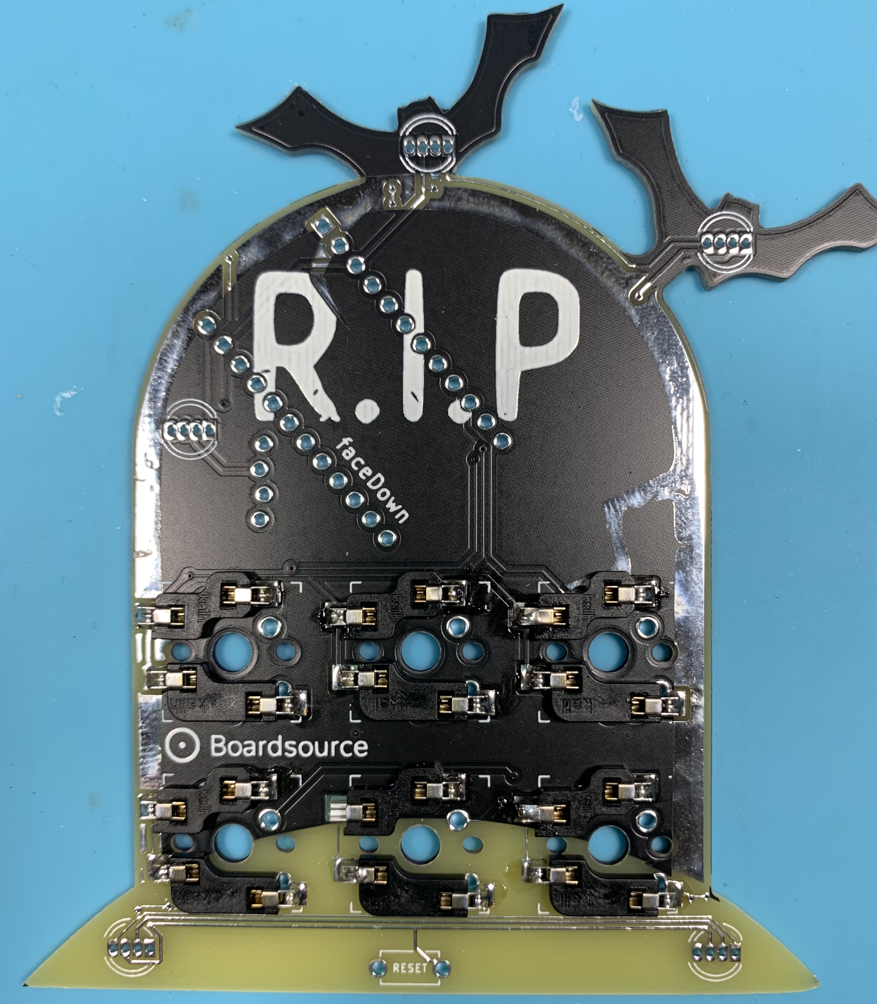
Each hotswap socket needs to be soldered in two locations, one on each side of the socket next to where each of the switch legs go.
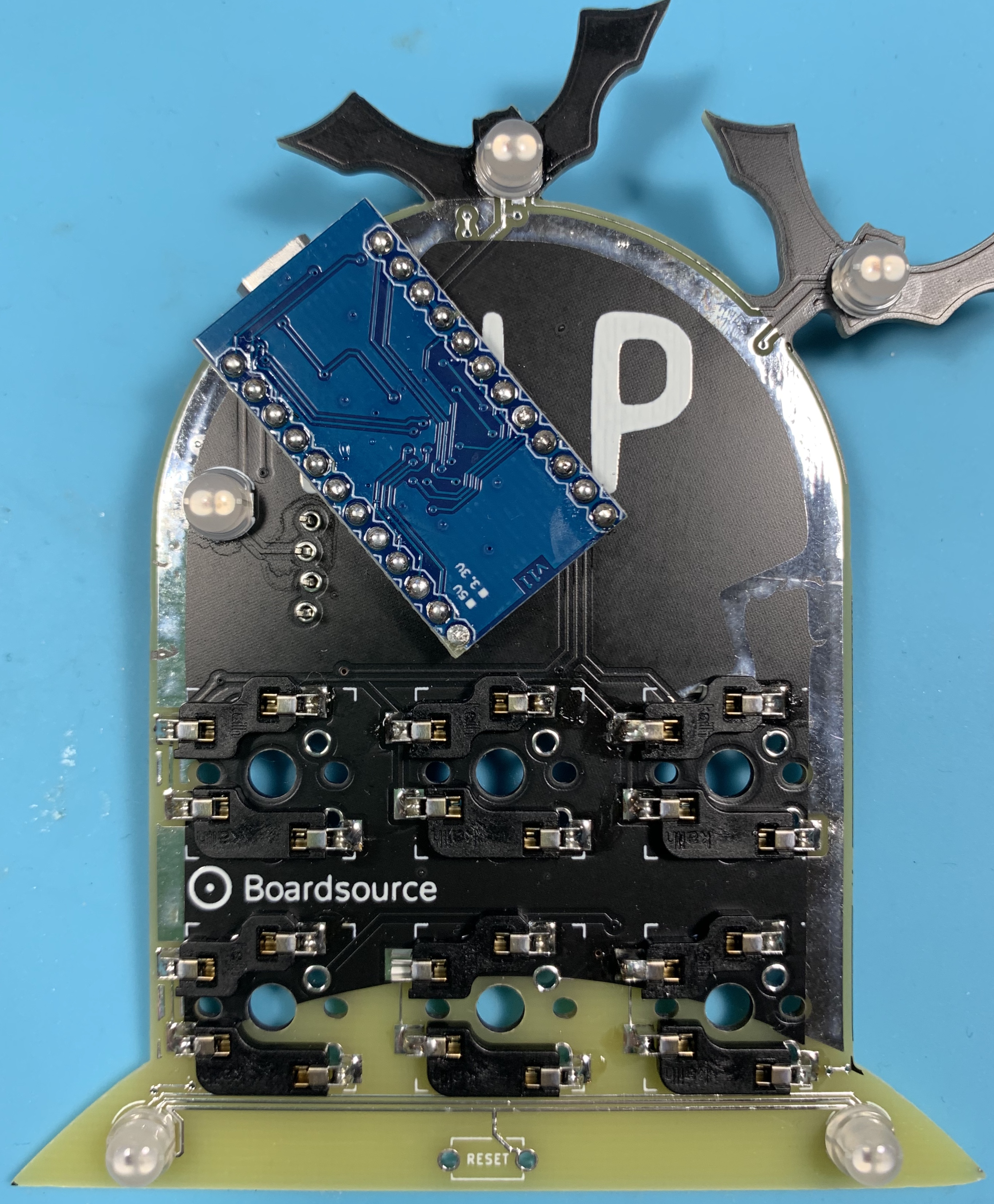
Step 3: The Micro Controller
In order to use the micro controller on your board, you must first prep the micro controller for installation. This process is essentially the same for every keyboard, you must solder the legs onto the micro controller. Elite-Cs and Pro Micros come with legs in the anti-static baggie. There are usually 3 sets, 2 long, and 1 short. We don’t use the short, but we will use the 2 long sections.
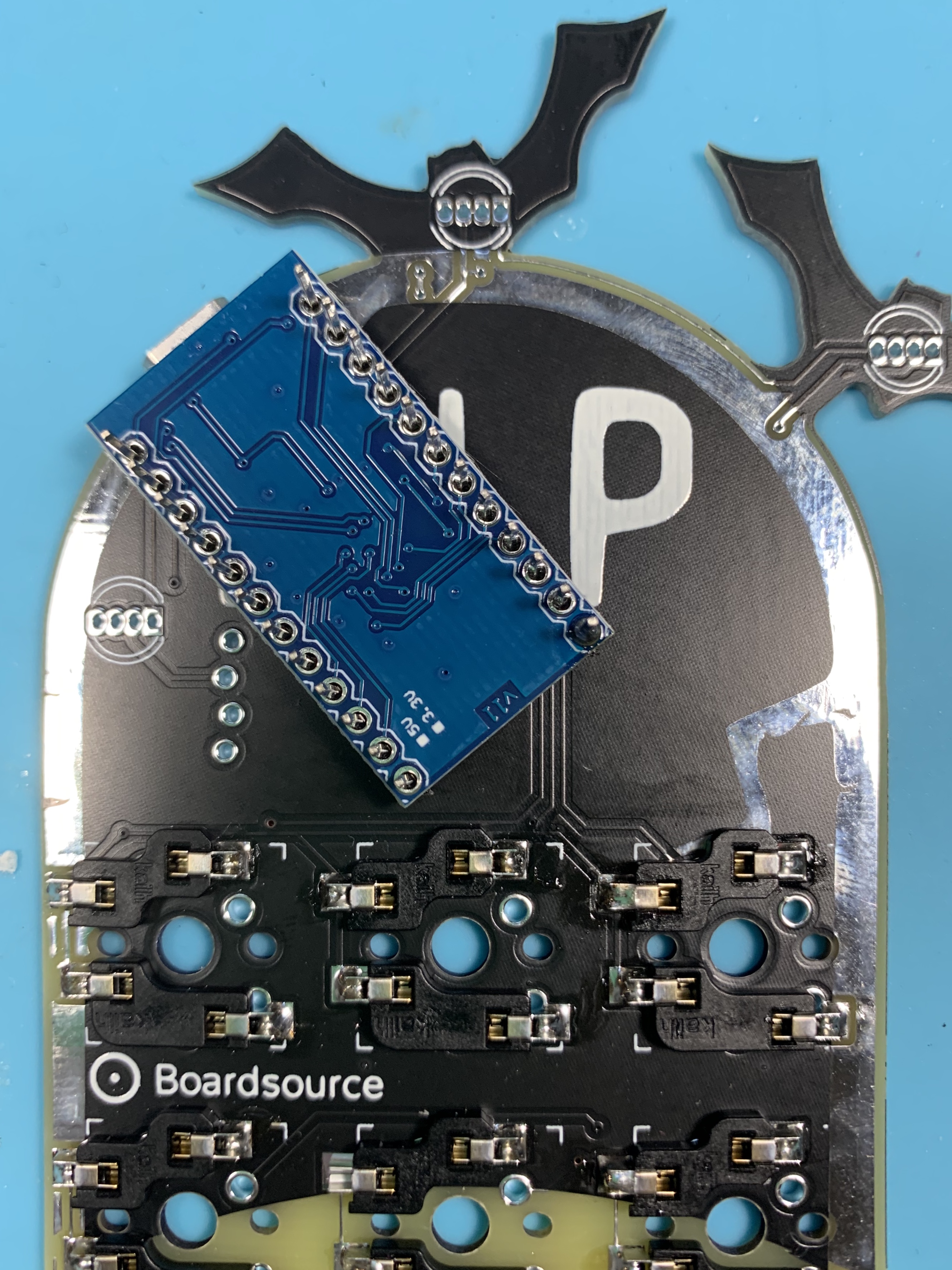
Micro controller leg sections have a black plastic strip connecting them, and that strip is intentionally not placed in the center of the leg. This placement creates a “short” end and a “long” end. The long end is what goes through the PCB and the short end is what comes up through the micro controller. On the spooky PCB the micro controller is installed with the component’s facing down. Make sure you solder yours legs in place exactly as shown in the image above. If you install the micro controller upside down, your keymap will not work. Additionally, micro controllers are one of the most annoying things to desolder and fix, so try very hard to get it right the first time.
When soldering the legs to the micro controller, make sure that the legs are at a 90 deg angle to the micro controller and that they are straight the entire length, and inserted all the way. If you don’t take the time to ensure everything is lined up properly and not crooked/diagonal it is likely that you won’t be able to install the micro controller because the legs won’t line up with the holes on the PCB. Again, these are very annoying to desolder and fix so it is important to take your time and try to get it right the first time.
I hold the legs in place, fill my soldering iron with some solder, and then messily “tack” the legs in place in two locations. This basically means I just try to slop some solder onto the legs in two locations to make them stick. It isn’t super pretty, but it is easily cleaned up and can be made to look perfect again. At first, you just need to get the legs to stick where you want, then you can move the micro controller, reposition it, and solder the remaining points in a more comfortable way.
Soldering into the PCB
Note: on this PCB I like to install my pins as flush as I can on both sides. The LEDs are used as feet so it is important you trim your pins on your micro controller as close as you can.
Step 4: Installing RGB LEDS
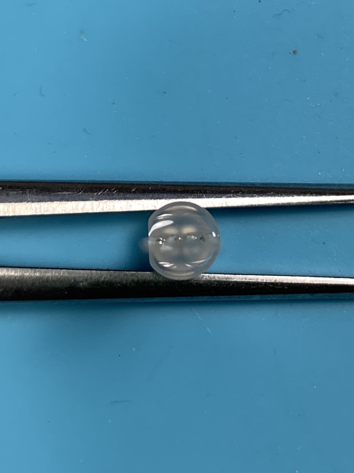
RGB LEDs need to be installed in the right orientation to work. There are markings for this purpose on both the led and the PCB
In the photo above you will see there is a flat side of the led. Take note of this on each LED before you install it. This flat side pin needs to be aligned with the square hole on the PCB LED footprint as shown below.
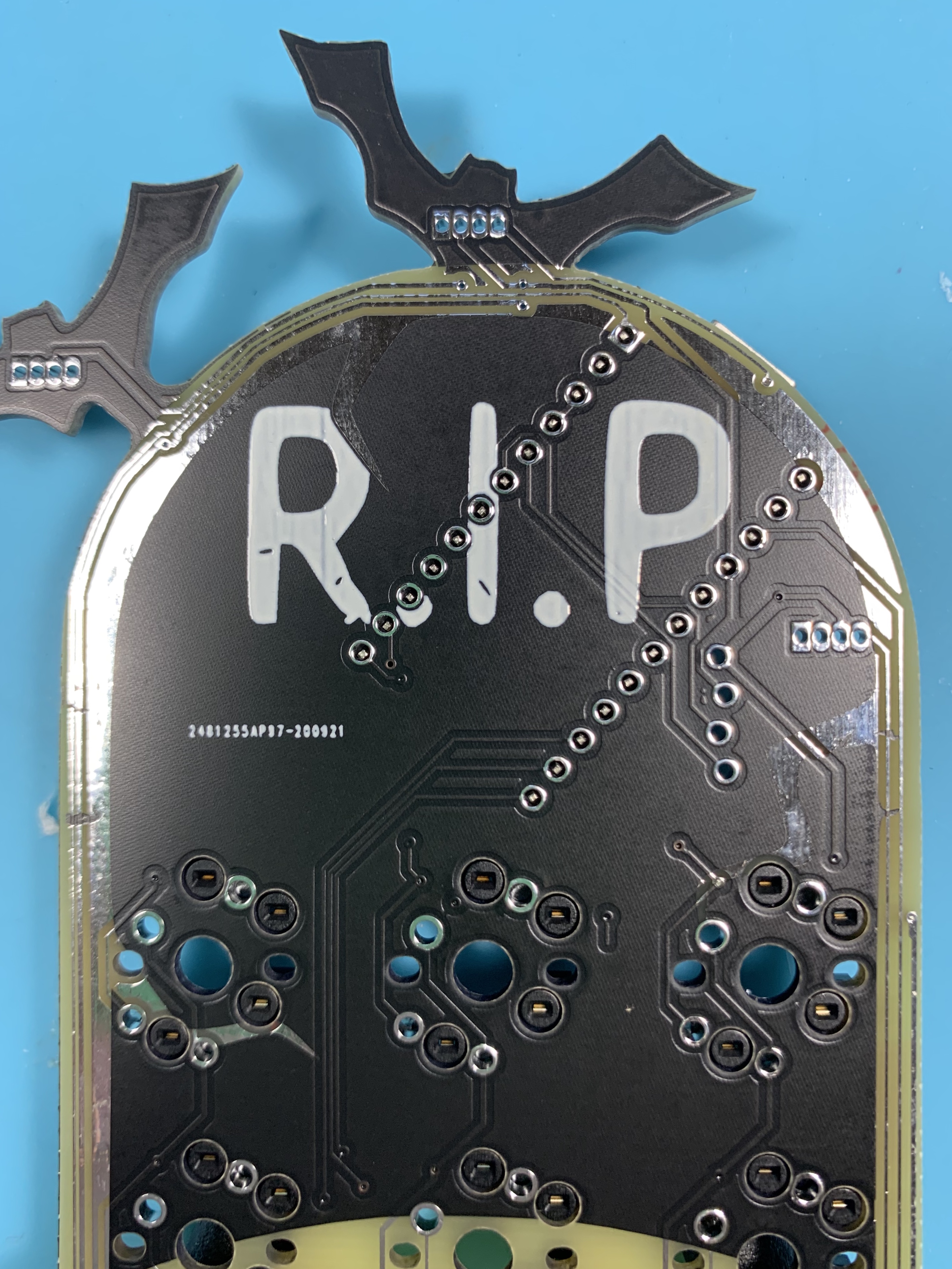
The LEDs are used as feet on this PCB so they are to be installed on the back of the PCB. When installing them place them through the PCB (this may take some force). Then flip over the PCB and tack them in.
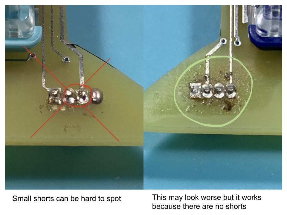
** Important Note: these pins are ver close to each other if there are any shorts your keyboard will not turn on. Pay close attention and use a small amount of solder, you can add more easily.**
Step 5: Installing the OLED
On the front side of the PCB (this side should have nothing installed on it at this point) place your header pins included with your OLED screen through the 4 holes on the right side of the PCB. Install the long end through the PCB until the black plastic is resting on the PCB.
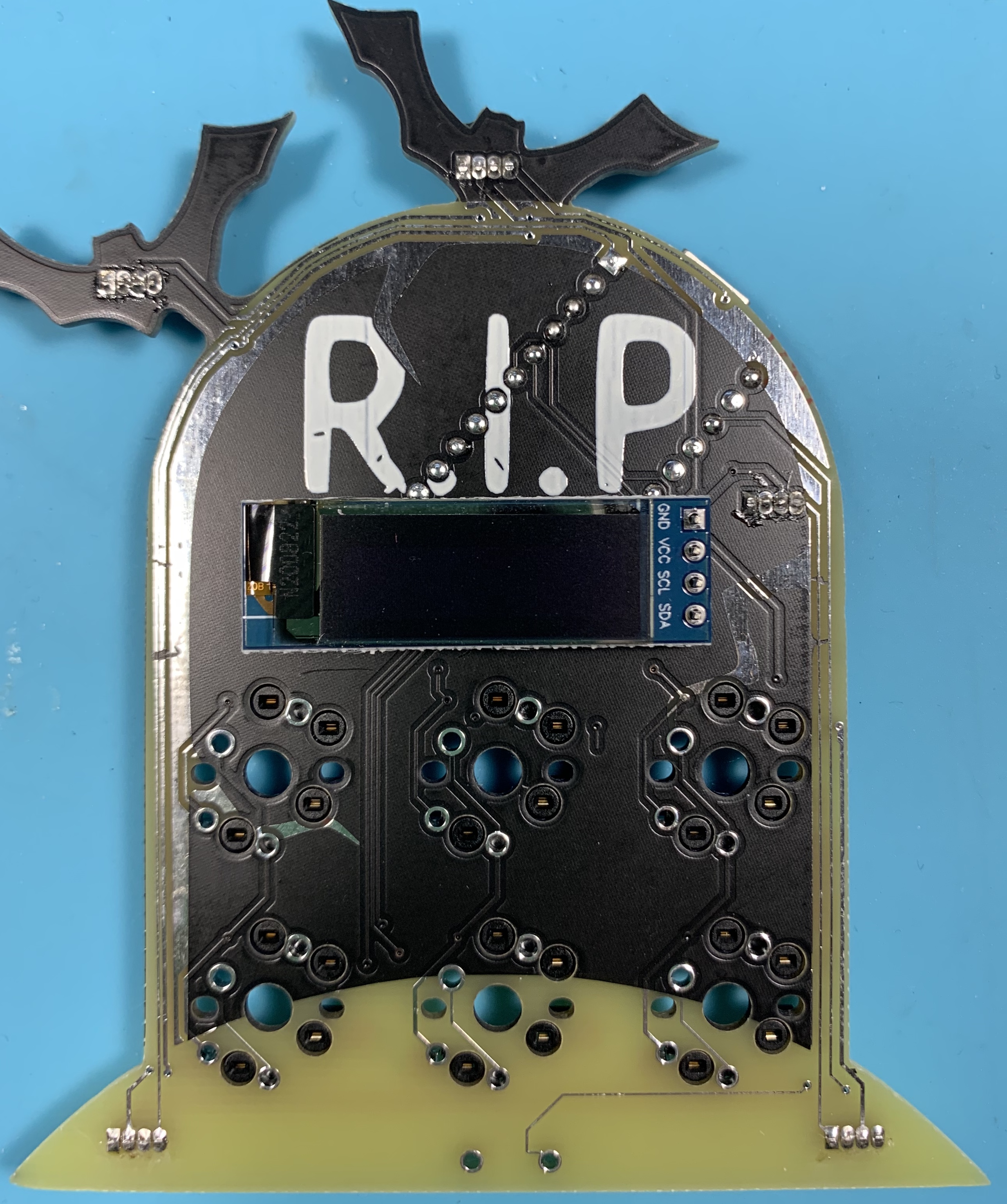
Next, install your OLED screen in the orientation pictured above. Like the micro controller I tack in just one pin to get it held in place so I can do the rest.
After soldering the OLED on the top side you should flip over your macro pad and solder in those same 4 pins on the back of the PCB.
Step 6: Reset switch
To install the reset switch I like to fill up one hole with solder, place the reset switch on top then heat that hole back up and most of the time it will stick down. After that simply add a little bit more solder to each side starting with the loose side.
Step 7: Flash and use
At this point, plug in the micro controller and make sure that the light is still coming on. If there is not, it means you have a short somewhere. Go over to your PCB and clean up all the LED solder joints.
Note:
While the RBG LEDs are easy because they are through-hole, the pads are very close to one another. Check them carefully for shorts.
Related Products


Copyright ©2025, Boardsource. All Rights Reserved.