
Ortho Build Guide
Ortho Build Guide
Boardsource
Overview
This build guide teaches you how to build the high profile and low profile versions of both the 4x12 and 5x12 Ortho boards listed on Boardsource. Both sizes of each version of the board are built the same way, the only difference of course being that there is one additional row on the 5x12, the low profile versions use different hotswap sockets, but the installation principles are the same.
IMPORTANT NOTE
If the area underneath your controller on the backside of the PCB says 'Face Up' then you have the new version of the PCB with edits made. These edits make it so that the micro controller is installed with the components face up on the PCB. The old version of the PCB which does NOT say 'Face Up' must have the controller installed face down with the blank side up. If you need help determining which version of the PCB you have please reach out on Discord. Sorry for any inconveniences this may cause.
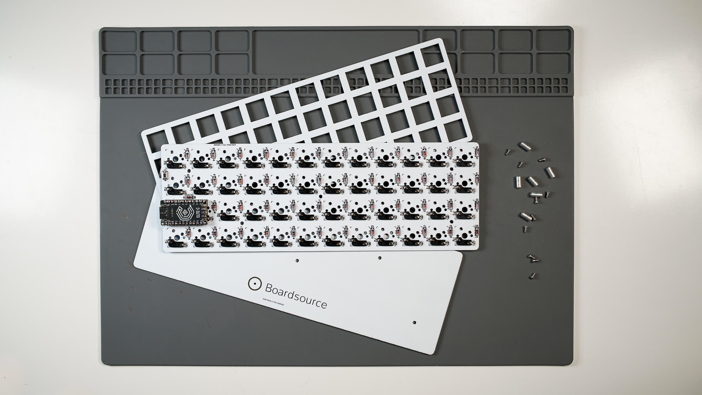
Kit Contents
- Ortho PCB (the size/version depends on what you purchased)
- FR4 Backplate (1)
- FR4 Plate (1)
- Elite-C / Pro Micro (optional) (1)
- Threaded Standoffs (5)
- M2 Screws (5)
- Diodes (50 or 60)
- Hotswap Sockets (50 or 60)
- Rubber Feet (4)
Step 1: Check Kit Contents
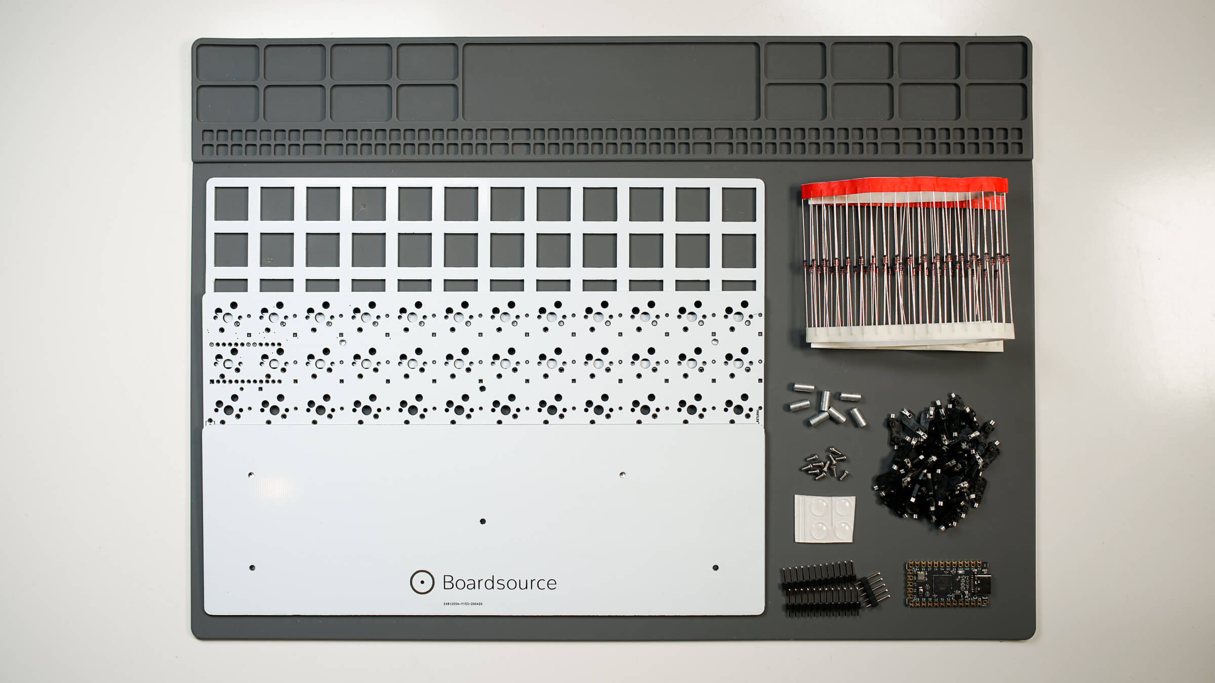
Prior to starting any build it is important to take a look at what you received and what you have in front of you. Nothing is more frustrating than getting halfway through a build and realizing you’re missing a single hotswap socket or a screw, or anything for that matter. If you think we forgot to ship something, or if you may have accidentally misplaced something, please reach out to us on Discord in the Help section, or Submit A Ticket in the My Account section of Boardsource.
Note: Boardsource often includes extras of certain items in our kits, it is not unusual to have an extra screw, hotswap socket, or diode. The quantities listed in the Kit Contents section at the beginning of this guide are the true accurate number of components needed to complete the build, if you have more than the listed quantities or have some left over at the end it does not mean that you forgot something or built the kit improperly.
Step 2: Assemble the PCB
PCB Assembly - Install and Solder Diodes
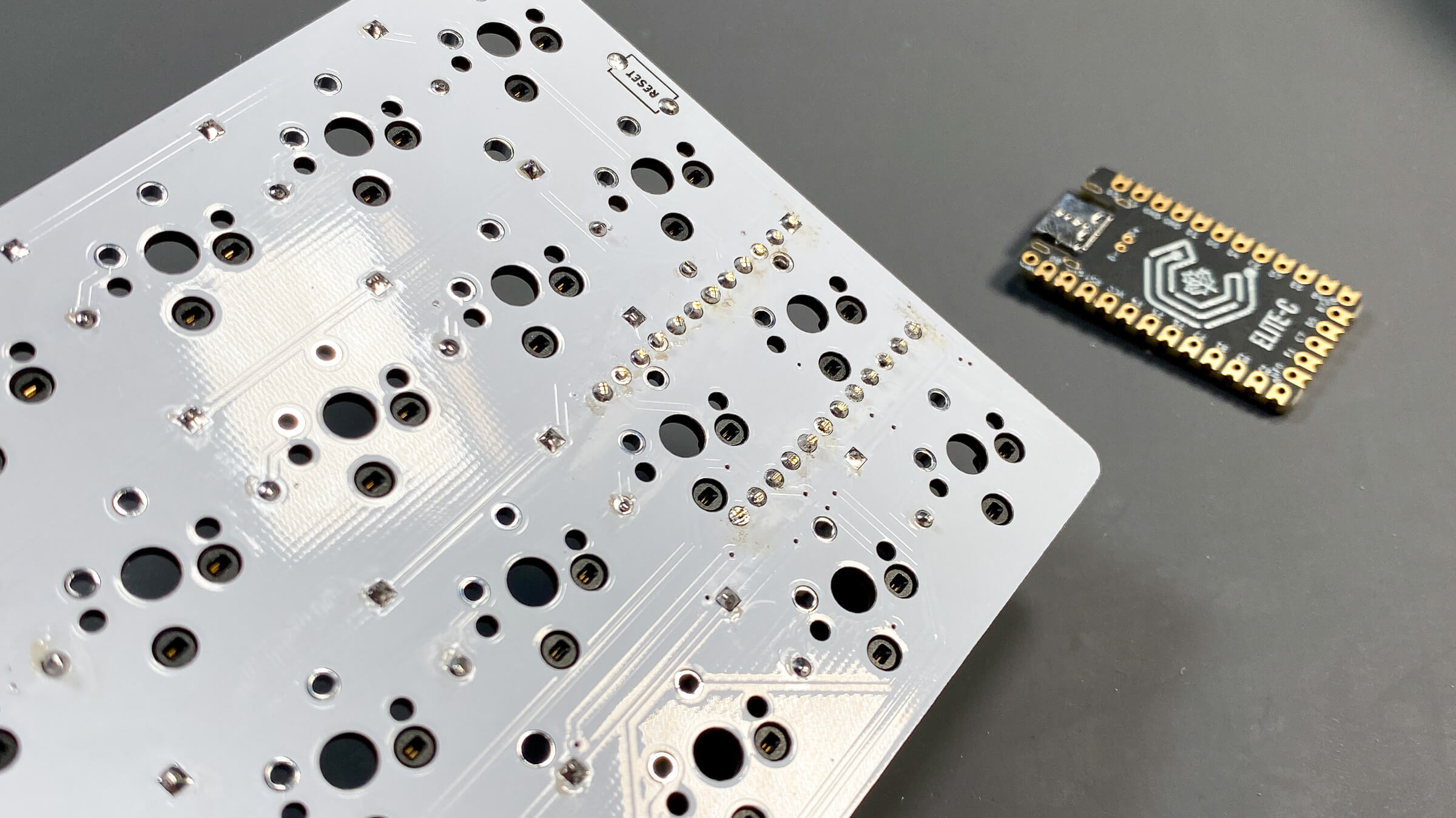
The first step of PCB assembly is to install the diodes. The diodes are installed on the ‘back’ of the PCB, meaning the side that faces down when it is in final typing position. In order to tell up from down on this PCB, we can look for the solder mask that indicates the diode locations as well as the square shaped pads for the hotswap sockets. That is the bottom of this PCB.
Like all through-hole diode PCBs, the diodes must be bent prior to installation. If you have a diode bender, awesome, if not it is no big deal you can bend them by hand. If you want a clean look, often needle nose pliers work quite well. It really just depends on how much patience you have.
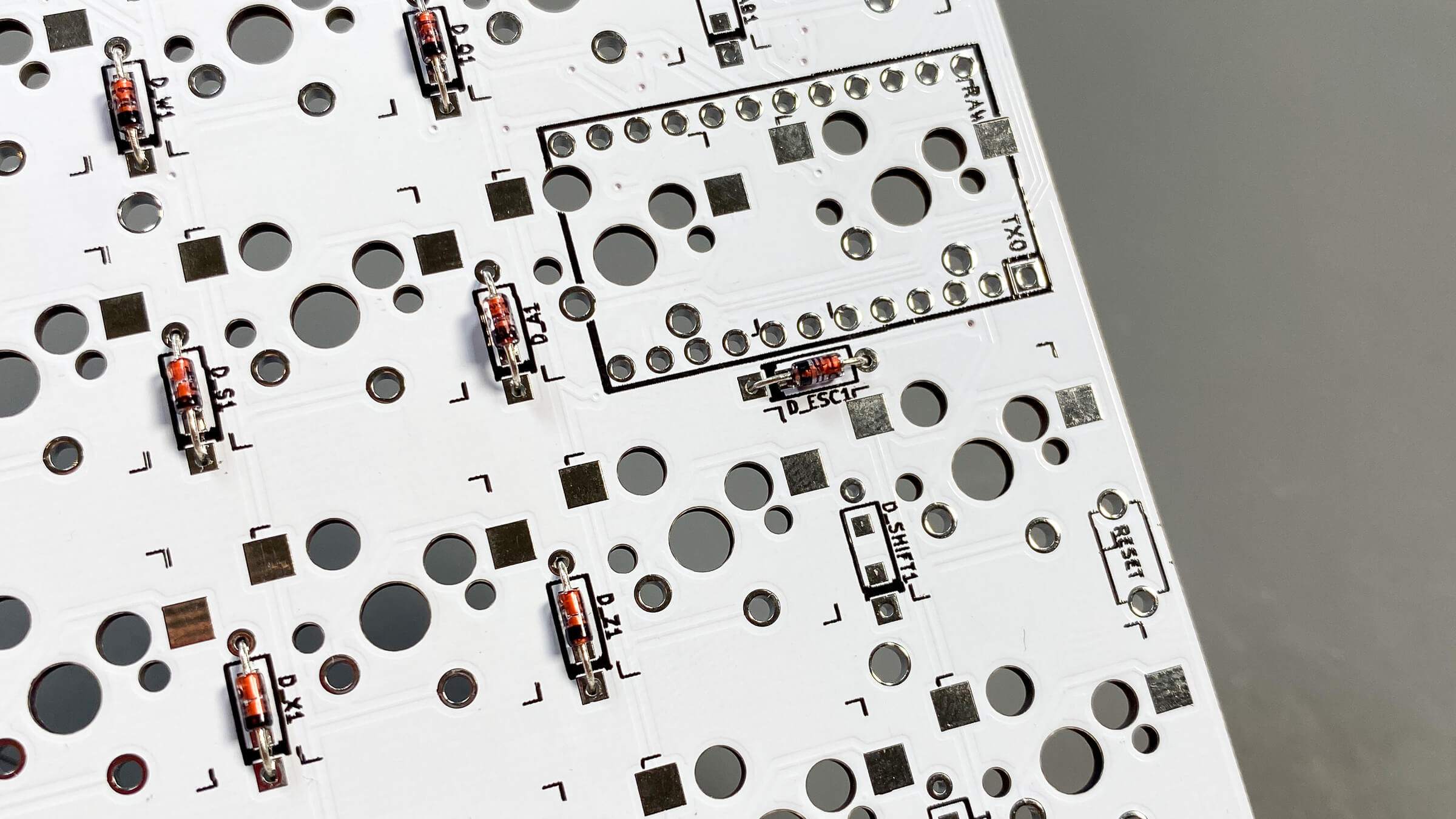
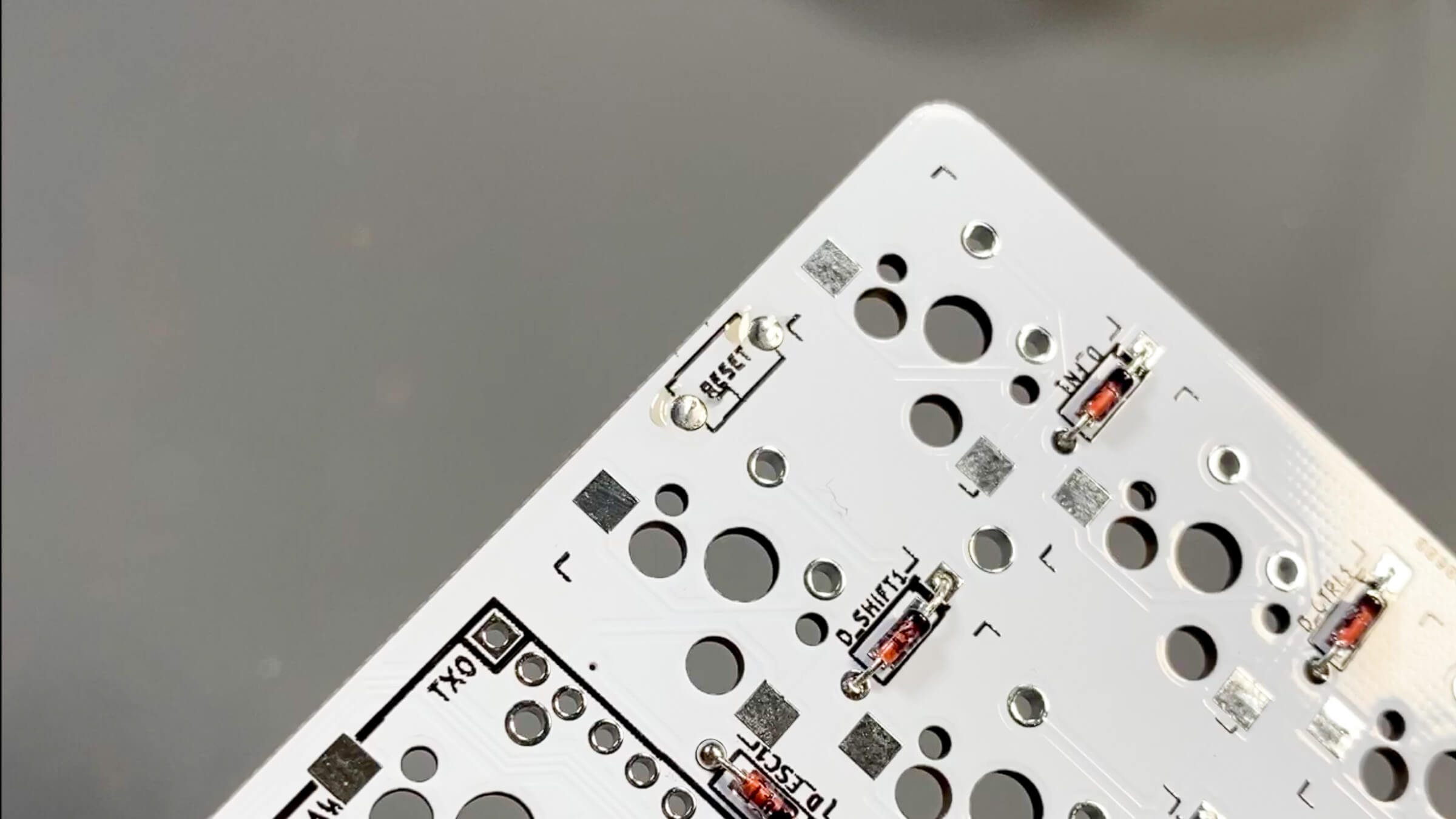
Diodes are installed into the PCB resting in place inside the areas indicated by black solder mask. You’ll notice that on one side of the diode location there is a circular hole, and on the other side of the diode location there is a square shaped hole. The black/darker side of the orange and black diode go towards the square shaped hole, and the orange side of the diode goes towards the circular shaped hole. All diodes must be installed in this orientation across the entire board. Take your time and make sure they all face the correct direction prior to soldering them, as it’s easier to take your time and do it right the first time than make a mistake and have to desolder to fix it.
I find it easier to do sections of the PCB rather than the entire thing at once. I place the diode into the designated place in the correct orientation, then bend the back of the legs in order to hold it in place. I do that carefully for about 10 diodes, then flip the PCB over and solder them then trim the legs. I repeat this process until all the diodes are installed.
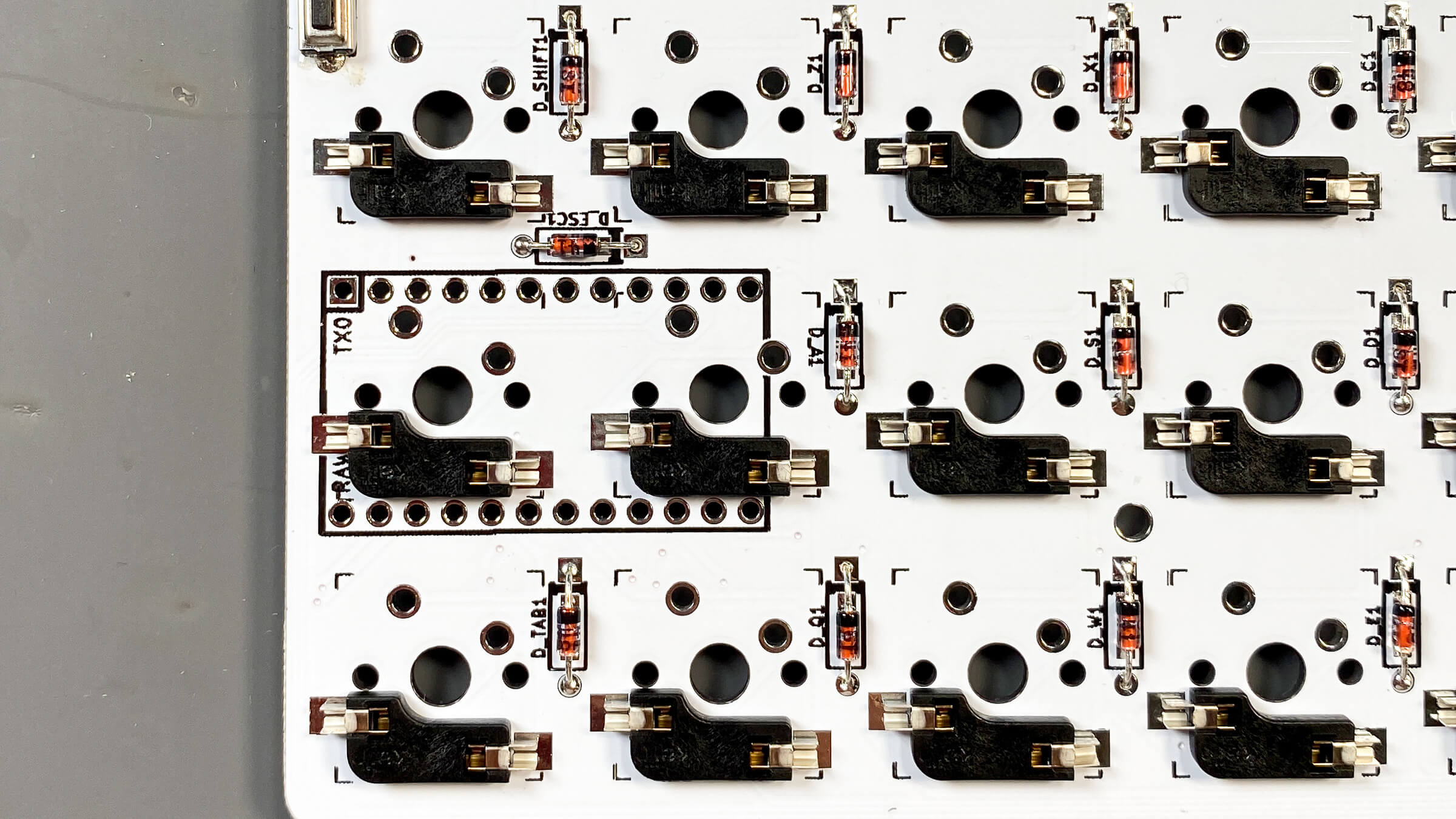
Don’t forget the one diode near the microcontroller that doesn’t follow the same rhythm as the others, it is shown in the photo above and faces ‘sideways’ instead of vertical.
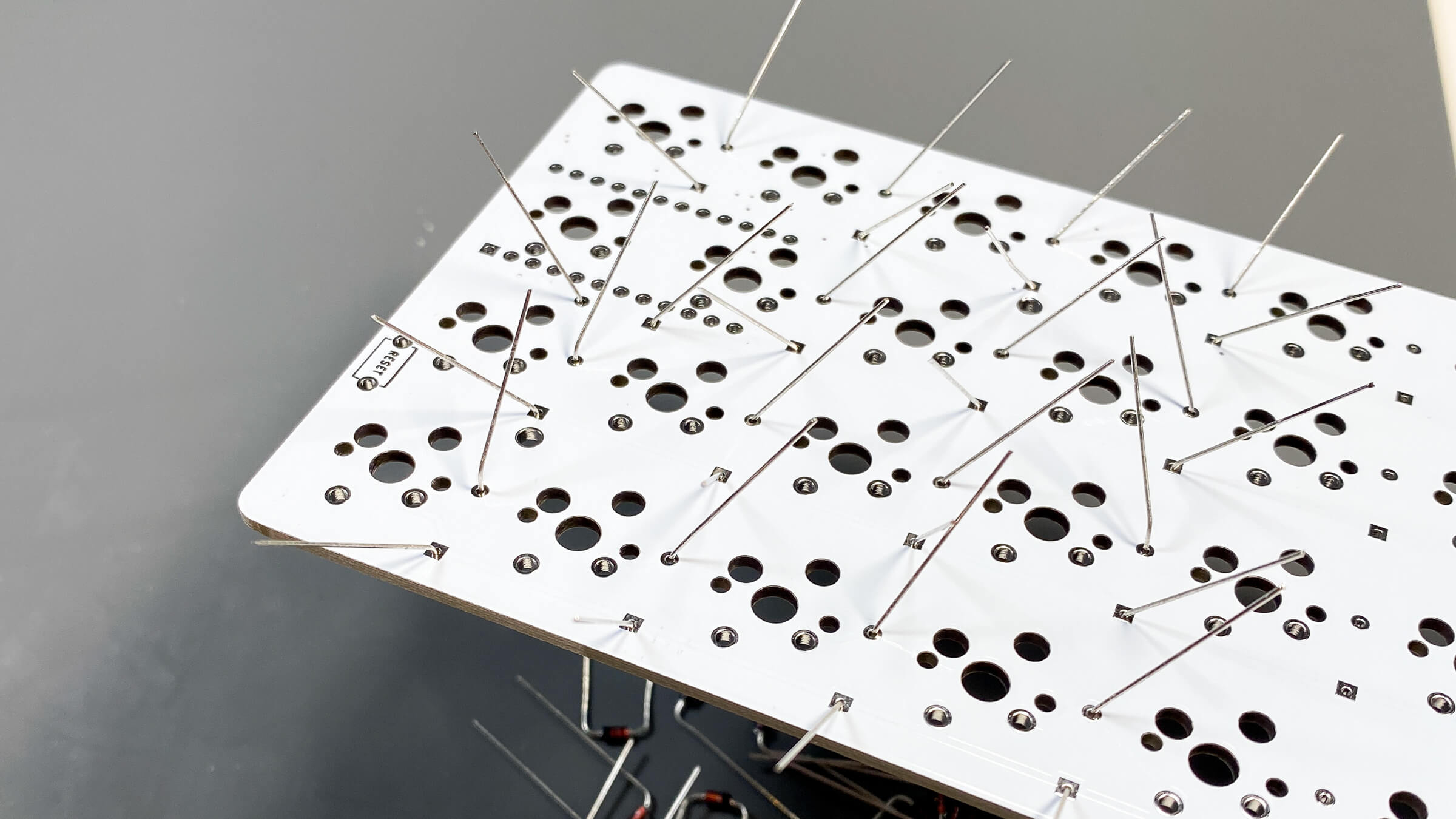
In the above photo you will see how I bend the back of the diode legs to hold them in place and allow me to flip the PCB over and solder them. I think it’s best to do this in sections because even after bending the legs they usually will move and wiggle around a bit, and I like to make sure the diode is fully seated against the PCB to make it all look cleaner. Plus, it can be difficult to navigate the field of bent diode legs with your soldering iron, so doing it in sections is best and easiest.
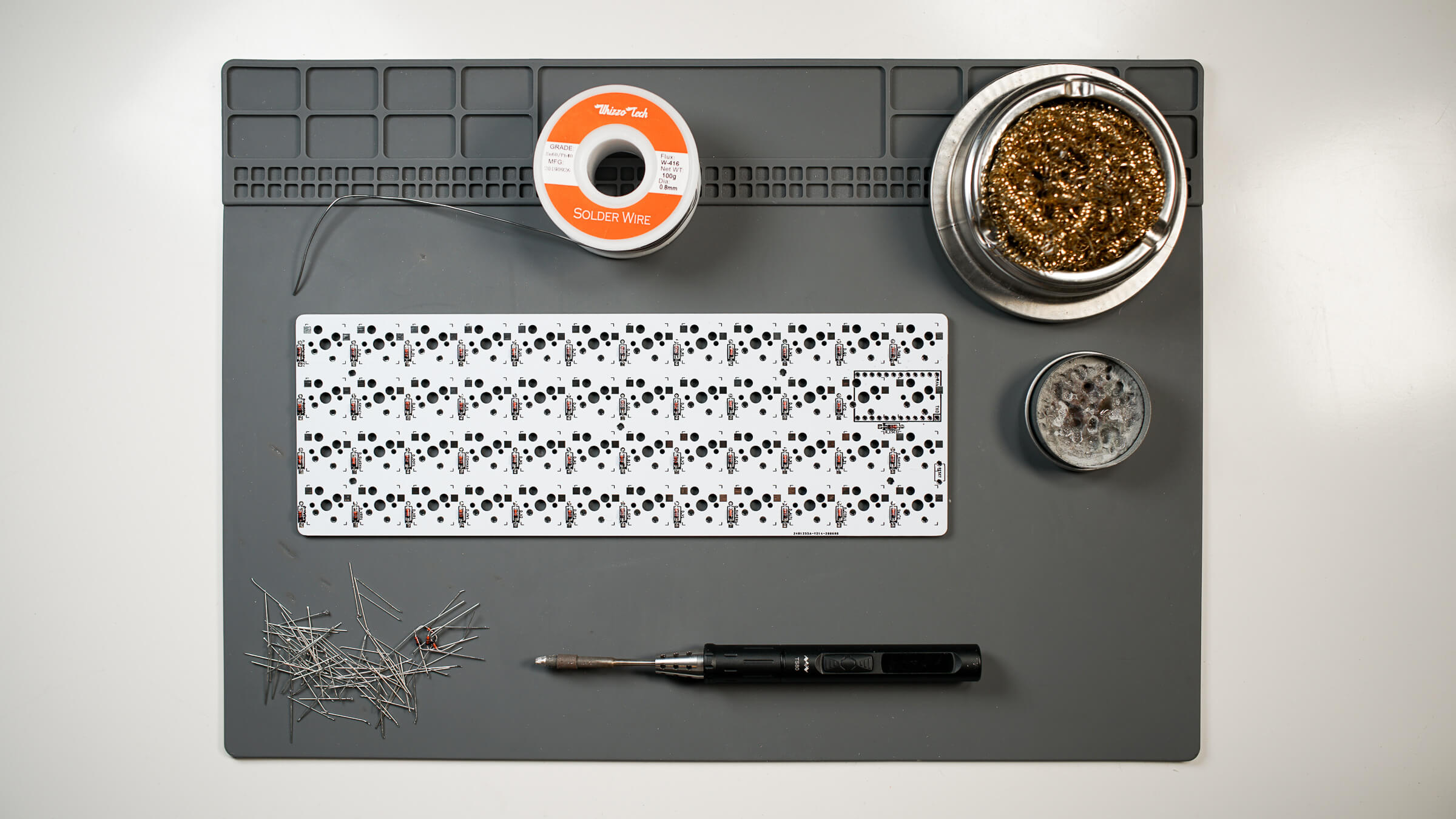
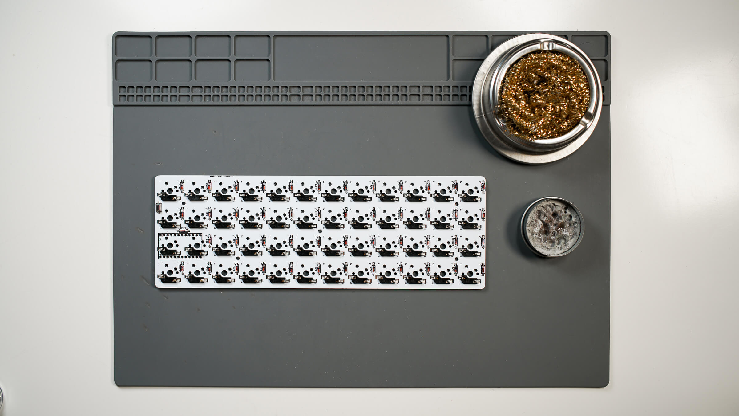
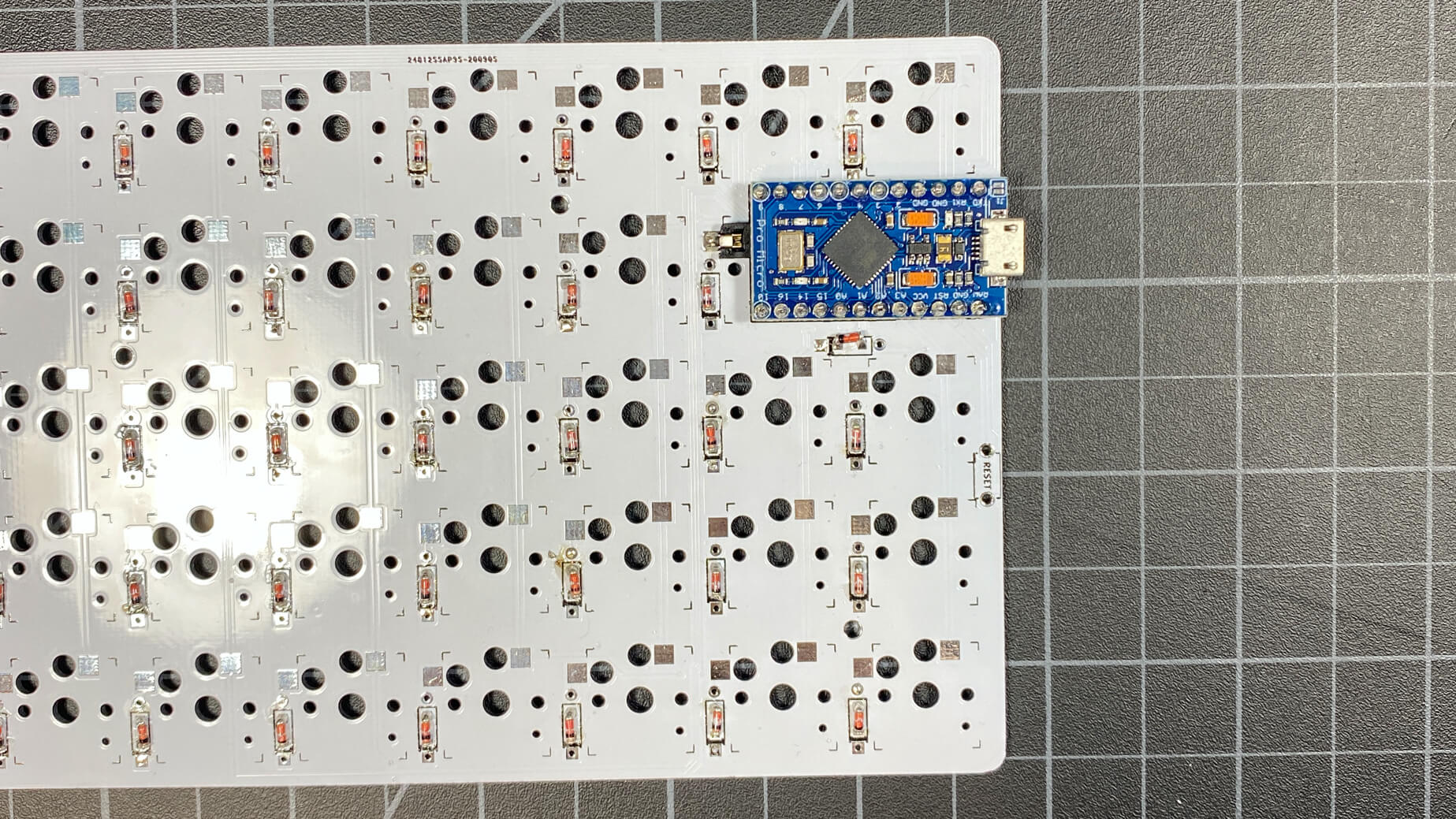
Now that we have successfully installed all the diodes, as shown in the photo above, we are ready to move on to the next step.
PCB Assembly - Install Hotswap Sockets
Next, we will install the hotswap sockets. Hotswap sockets are installed onto the PCB on the same side as the diodes, the “back” of the PCB.
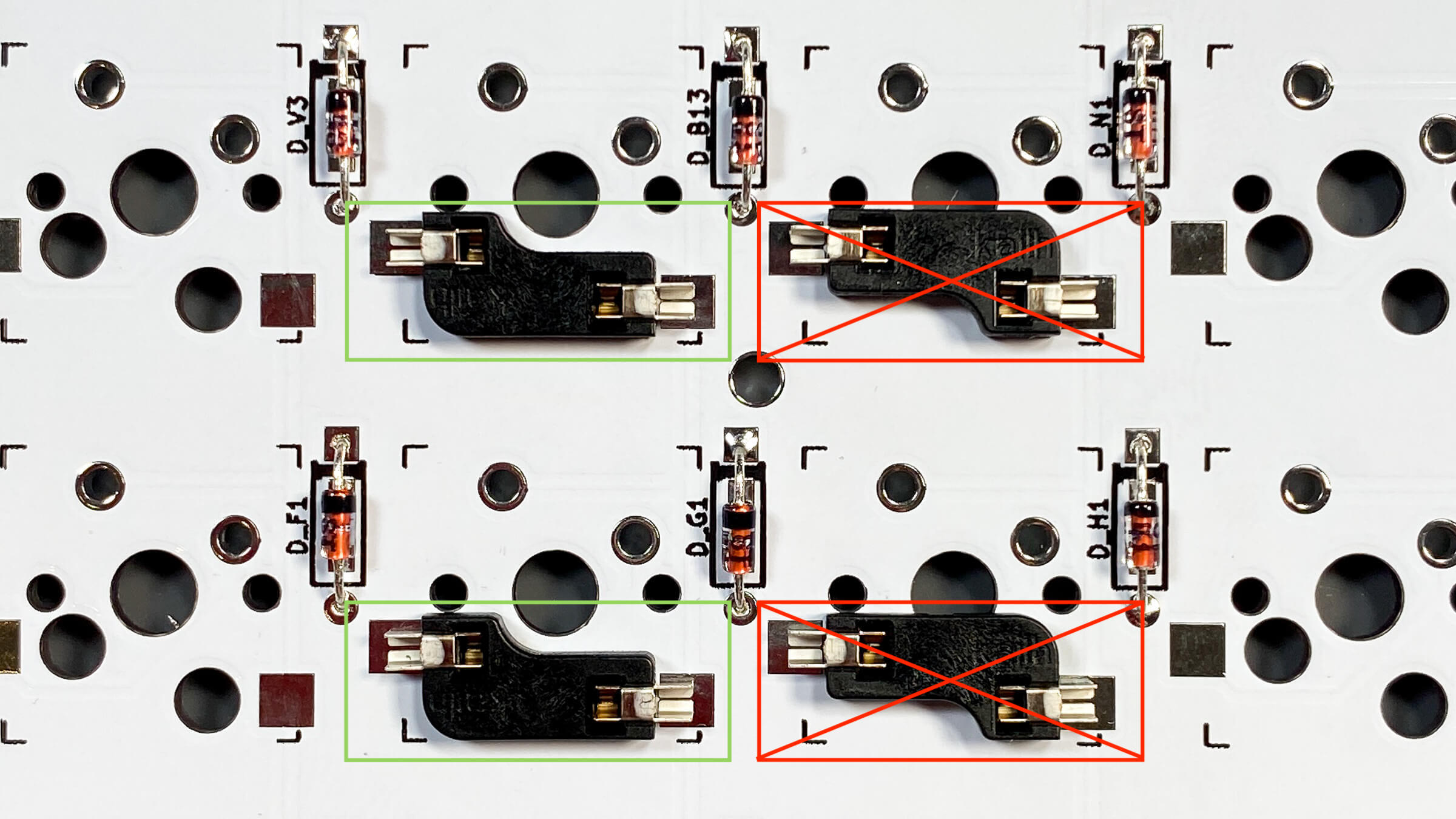
The pads match up for the hotswaps no matter the direction you face the socket, however, you’ll notice that one direction causes the socket to overlap the hole for the switch post. Make sure to not install the hot swaps in such a way where it covers up the switch post, that is the wrong orientation. Take a look at the photo below to see what I mean.
Go through the entire PCB and install all hotswap sockets in the necessary location and solder them into place. I usually like to fill the entire “well” of the socket, as sometimes when installing switches the hotswap will take a significant amount of pressure and you don’t want it to break off under pressure. Careful not to over-fill though.
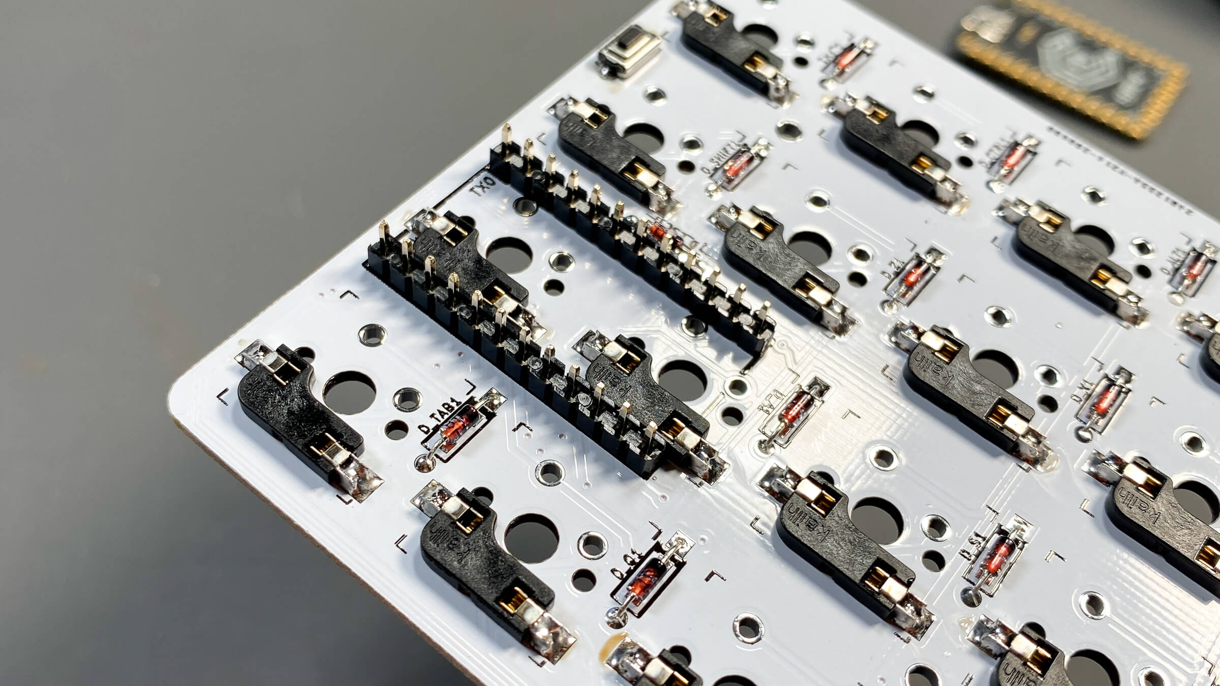
Very Important: You must install the hotswap sockets in the middle area of the microcontroller prior to installing the microcontroller or they will be covered up.
Now that you’ve installed every socket onto the PCB, and you have made sure to install the sockets that will soon be hidden by the microcontroller, you’re PCB should look like this.
Step 3: Install Controller
Install Controller - Install Header Pins Into PCB
The first step of installing the microcontroller is to install the header pins into the PCB. This is fairly easy and there is only thing to look out for — which side of the pins you put through the PCB.
If you take a look at the header pins, you’ll notice that there is a black piece of plastic on the pins, and the pins on one side of the black plastic are shorter than the other side. The shorter side is what you connect the microcontroller to, and the longer side is what goes through the PCB.
Make sure to solder the header pins into the PCB while the pins are completely flat against the PCB and the black plastic is firmly seated against the PCB, and the pins are totally perpendicular to the PCB. If they are installed unevenly or crooked the microcontroller will not properly fit.
After you’ve successfully soldered the header pins into the PCB, trim the excess legs on the opposite (front) side of the PCB as flush as you can with the face of the PCB. Please remember, these legs can fly very far and very fast when you cut them, so be sure to cover your eyes and preferably block them from flying so you don’t step on them later.
Here is how the front of the PCB will look after you flush-cut the legs of the header pins.
Install Controller - Solder the Controller In Place
Note: It is always a good idea to try and flash your microcontroller prior to installing it onto the PCB, as they are incredibly difficulty to de-solder and replace. It is very rare but sometimes microcontrollers do not work and are dead on arrival, so it’s best to figure that out prior to soldered it.
Now that the header pins for the microcontroller are installed into the PCB you can solder the microcontroller into place. On this PCB, the components on the Pro Micro or Elite-C face up. The side of the controller with “more stuff” on it will facing up and visible, the blank side (or side with the Elite-C logo) will be facing down and hidden.
IMPORTANT NOTE
If the area underneath your controller on the backside of the PCB says 'Face Up' then you have the new version of the PCB with edits made. These edits make it so that the micro controller is installed with the components face up on the PCB. The old version of the PCB which does NOT say 'Face Up' must have the controller installed face down with the blank side up. If you need help determining which version of the PCB you have please reach out on Discord. Sorry for any inconveniences this may cause.
This photo was taken at a different time than the rest of the build guide, and the build guide was produced for the first version of the PCB. The only thing that has changed is the orientation of the controller. All other photos showing the controller may be inaccurate depending on your version of the PCB. If you need help please reach out on Discord. If you received your package after Sep 15th 2020 it is extremely likely you have the new version of the PCB and must install the controller with the components face up, disregard any photo showing anything different.
Step 4: Install Reset Switch
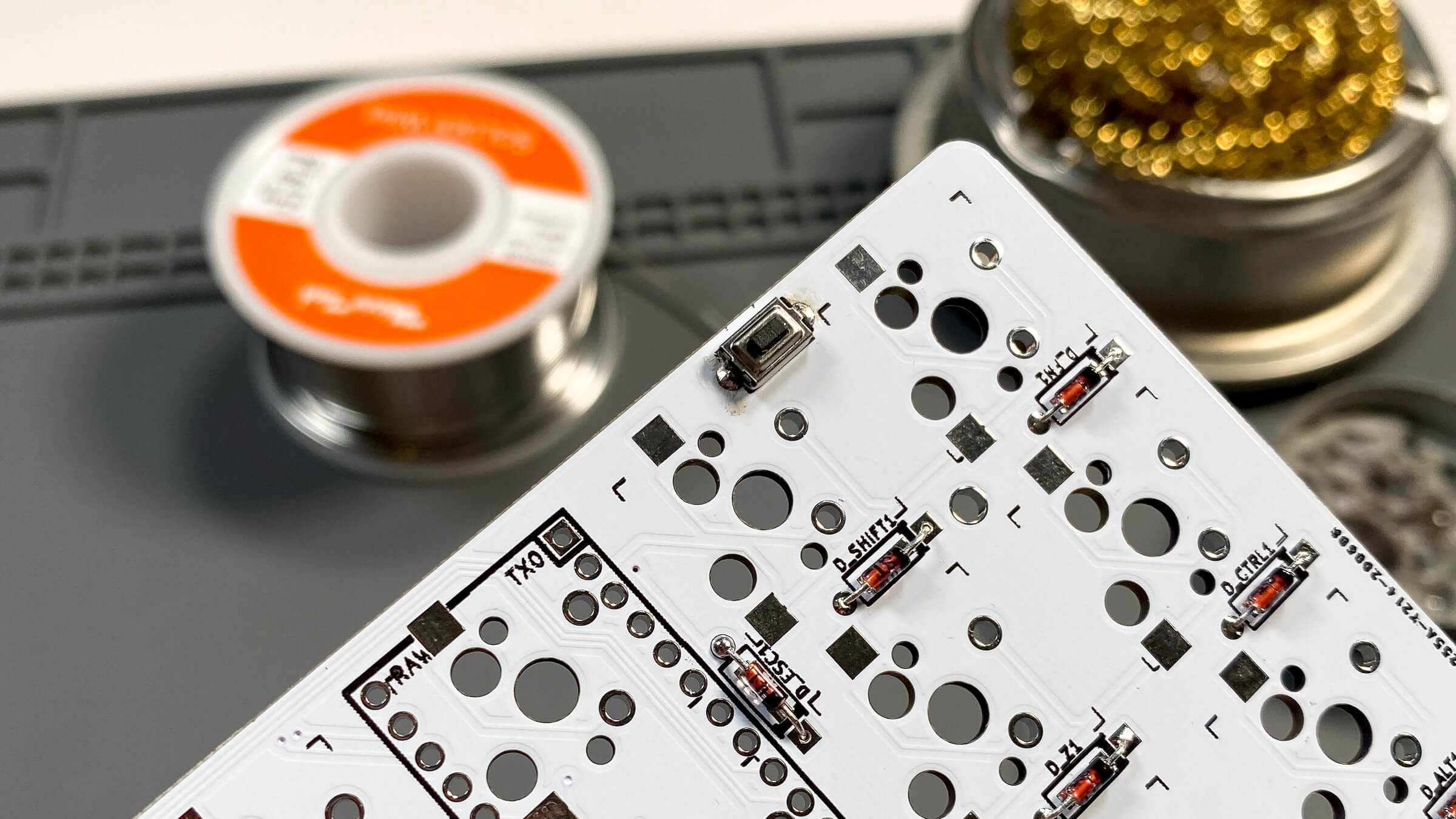
Before being totally finished with the PCB assembly and all the soldering, we must install the reset switch. The reset switch is installed on the back of the PCB, the same side as the diodes, hot swaps, and microcontroller.
The best method to do this that I have found is to fill the holes with solder, and then re-heat the solder and install the switch.
First, fill the holes so they look like this.
Next, you can simply hold the switch in place with needle nose pliers or tweezers, and heat the filled hole on one side while applying light pressure to the switch. This should re-flow the solder in that hole and at least make a bit of contact with the reset switch’s legs. If you can’t really tell if contact has been made or it seems a bit loose, you can add a bit of solder on afterwards. Make sure to do both sides of the reset switch.
When you’re done, it will look like this.
With all of the above steps done, we have a completed PCB and we are done soldering! Here is a photo of how the completed soldering will look.
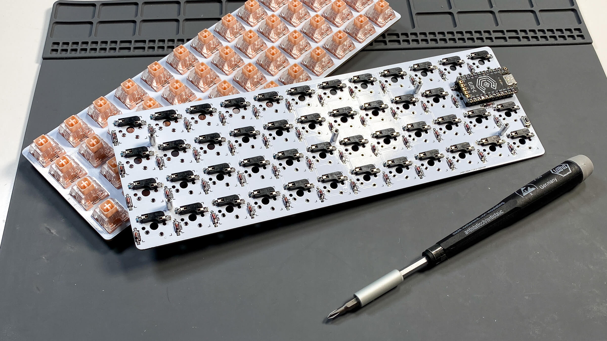
Step 5: Install Switches
With the PCB completely assembled, we can move onto installing the switches into the plate.
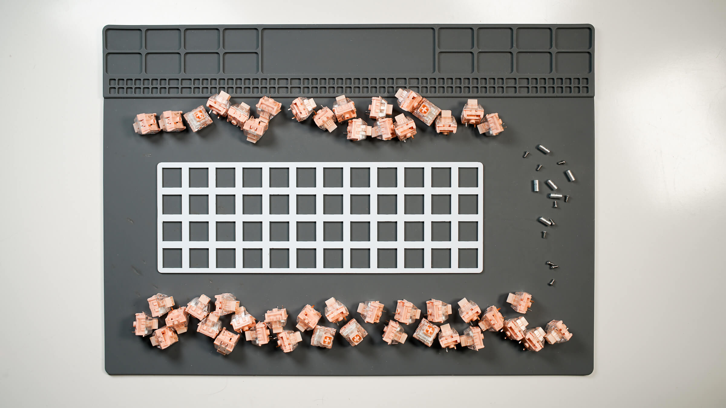
Install a switch into each switch hole in the plate. Make sure that the direction of the switch legs is consistent. Take a look at this photo to see how it’s done.
Step 6: Install Threaded Spacers into PCB
Find 5 of the threaded spacers provided in your kit and 5 of the M2 screws. Depending on the color of the Case selected in your kit, your hardware will either be silver or black.
Connect the threaded spacers to the PCB as shown below. The spacer should protrude from the back of the PCB, and the screws will go in from the front of the PCB where the switches sit.
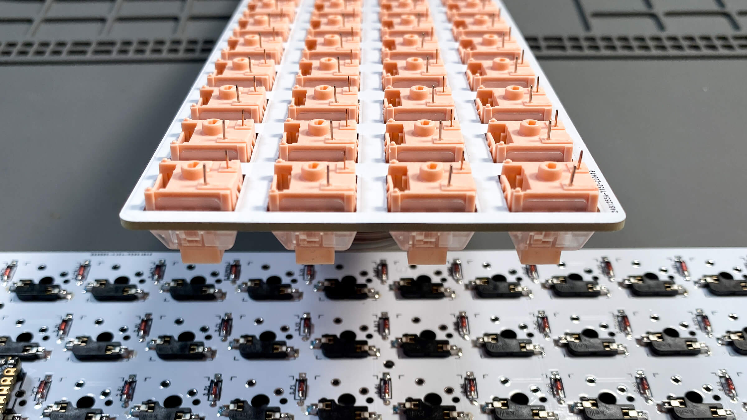
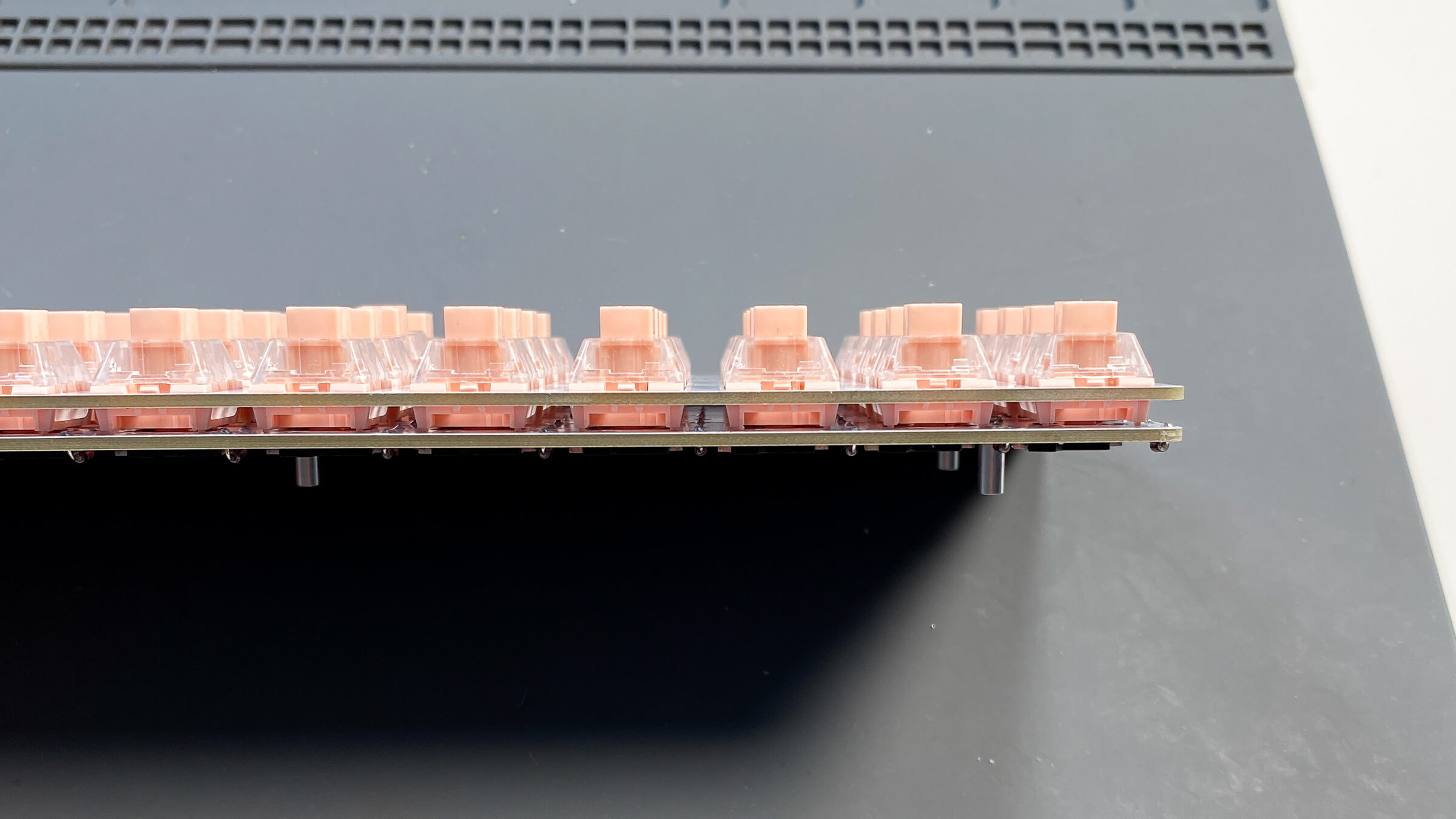
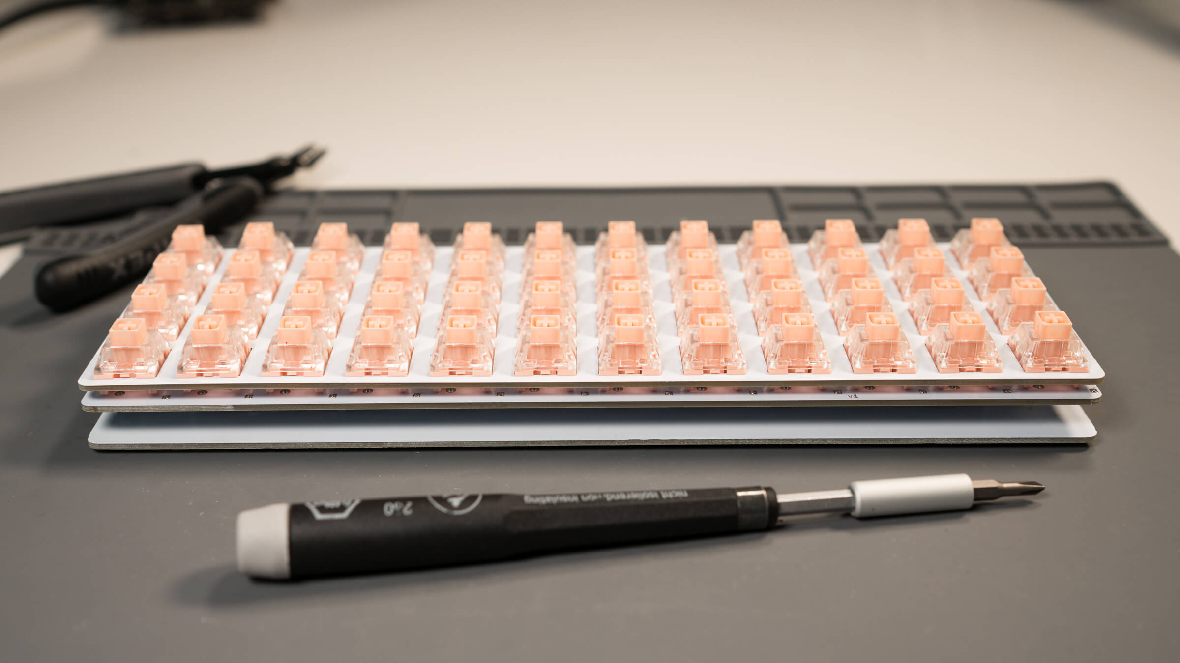
Step 7: Make the Switch Sandwich
With the PCB assembly totally done, everything soldered, the threaded spacers installed onto the PCB, and the switches placed into the plate, we can join the plate (with switches) to the PCB.
Before doing this, make sure that all the switch legs are facing the same direction, and that they are not bent. If they are bent they will not seat properly into the hotswap socket. Visualize how the switch legs will be inserted into the hotswap socket to ensure proper orientation.
Line everything up and push firmly but don’t force it, the switch legs should begin to go into the hotswap sockets. Go around the entirety of the board and make sure that each switch is properly seated into the PCB’s hotswap sockets.
Note: If you do not feel comfotable doing the sandwich technique all at once, just install a few switches around the edges of the plate and maybe a few in the middle area, connect the plate to the PCB with only those switches installed, then go around and do the remaining switches one by one. I just prefer to do them all at once and I ‘have the feel for it now,’ but for some people it’s best to do it one by one.
Step 8: Install the Backplate
After you’re fairly certain each switch is installed properly and the legs are seated in the hotswap socket, you can connect the back plate. Use the remaining screws to attach the backplate to the threaded spacers.
Place the rubber feet onto the backplate.
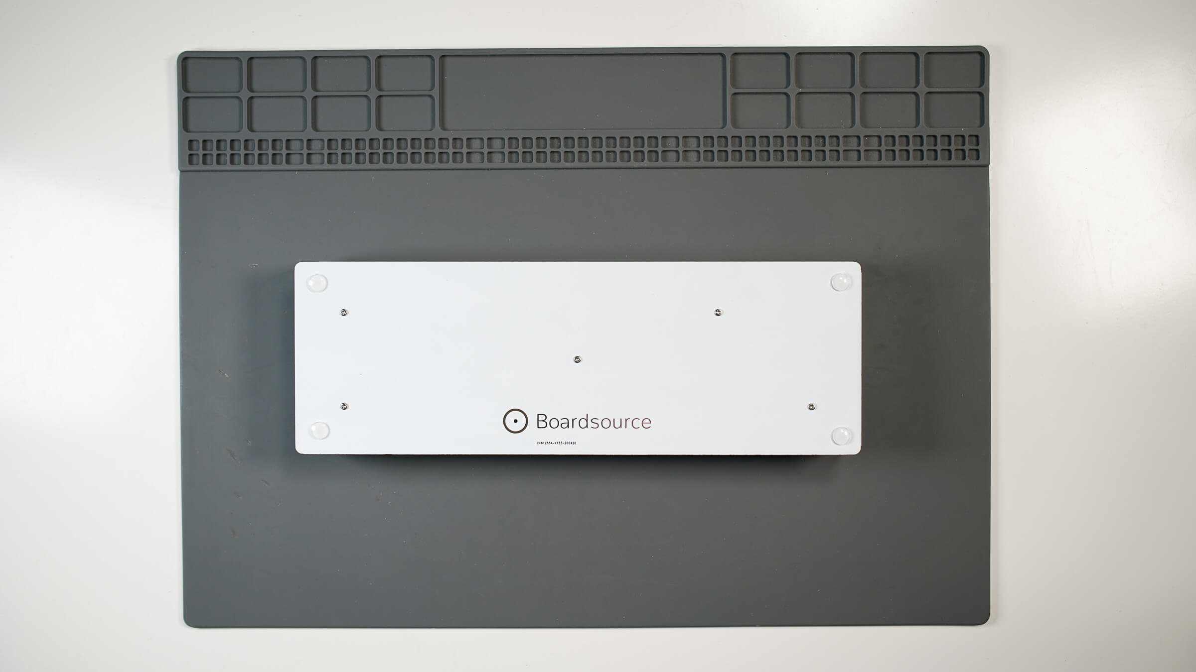
All done!
Now that we have successfully built the board, we can work on making our keymap and flashing the board! Refer to this guide if you need help flashing the board.
I hope you enjoy your board! If you’ve run into issues, come get some help in the Help channel in our Discord, or Submit A Ticket in the My Account section of Boardsource.
Related Products


Copyright ©2025, Boardsource. All Rights Reserved.